 JD Presents | Development In Reach
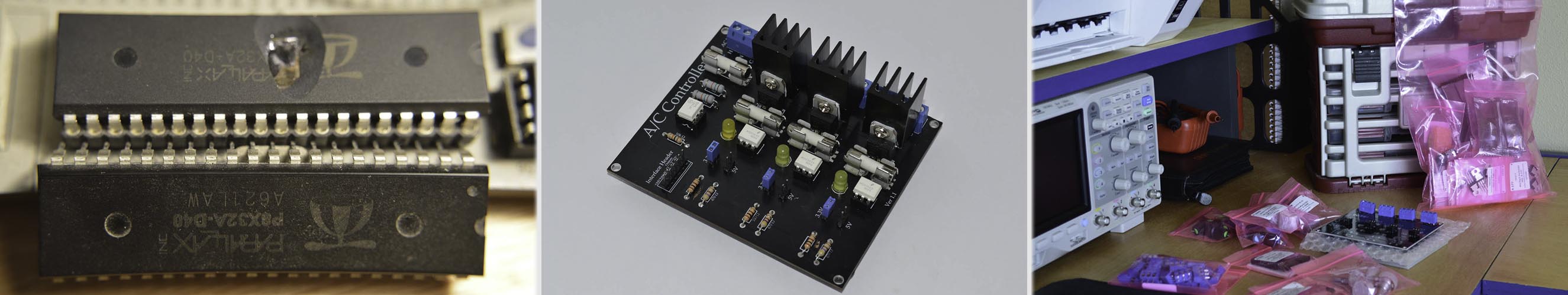
A/C Controller
Over a decade ago I saw a project that captured my imagination. It’s not a new concept by any stretch, but I find it fascinating. Controlling high voltage (120VAC) with a low voltage (5.0 / 3.3VDC) signal. Some of you may remember the X10 devices that was available from Radio Shack years back, they were an easy way to create home automation. X10 is a communication protocol enabling communication between smart home devices. It was a revolutionary leap towards a Jetsons lifestyle, and forty years after being brought to market, X10 is still going strong. X10 carries a signal over the AC main wiring in your home so you can control light switches, lamps, outlets and more.
.JPG)
.JPG)
.JPG)
.JPG)
.JPG)
.JPG)
.JPG)
.JPG)
.JPG)
.JPG)
.JPG)
The device I saw used a simple Triac and opto-isolator to turn on and off a 120VAC signal, which is basically how all these devices work. If you add a way to detect when the AC signal is at 0V, you can then determine when to pulse the line of the Triac creating a dimming function. That is where the H11AA1 comes into play. The H11AA1 is a bi-directional input optically coupled isolator that makes it easy for a microcontroller to see when the A/C signal is close to the 0V threshold.
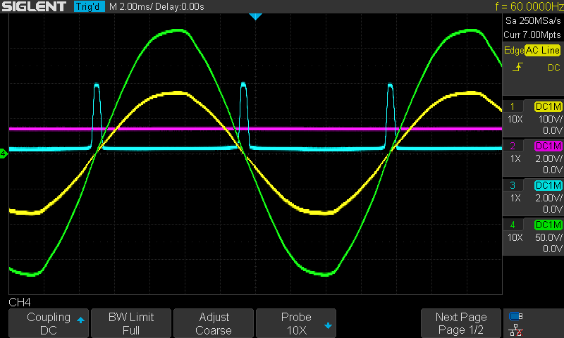
The image above is a screenshot from the scope that shows how the zero-cross works. The blue signal is the zero-cross detection; anytime the AC main signal crosses zero volts, there is pulse created by a transistor inside the H11AA1. At which time there is a specific time (~8.3 milliseconds) between the next pulse. The reason why this is needed, is if you just pulse the AC line randomly, you may or may not catch the signal correctly, making the dimming function very sporadic at best.

Once I had the signals and program working correctly, I wanted to make my own PCB. I had taken an electronics and PCB design class a year before that taught me how to use Circuit Maker by Altium. I have had good luck with it so far, there are many PCB layout and design programs out there, and each one has pluses and minuses. I also tried Dip Trace for a rocket PCB that measured relative altitude in model rockets, but I like Circuit Maker better. There is a bigger community that uses it, and a cloud service that lets people share projects. It requires you to login to use it, which I’m not a fan of, but it’s a small price to pay for a free development tool that comes with many perks.
The first board run, like many first runs, had a mistake. I swapped the pins 1 and 2 on the TRIAC. In my class, the instructor said this was inevitable, so I learned from my mistake, and I had to make another run. I made the second board with optional room for a heat sink on each TRIAC so someone could run a higher current draw and remain safe. I also added a connection for the ground wire from the main to provide additional protection. I also update the silk screen to include resistor values. I had both boards made by PCB Way and have been very happy with their support and prices. I priced around with around 7 companies, US and over-seas and I found them to be a solid option. The only down fall is the shipping time, but you can get around that by using DHL.
I have a couple projects for these boards already. The top 2 reasons are to allow me to have custom controls for lighting at my new desk and to conserve power on devices that I am not using. My scope and power supply are plugged in and have parasitic power draws. I find that unacceptable, but far too often devices offer Wake on LAN control which requires something to be powered all the time. To combat an unused feature in those devices, I’m running all my lights and devices through one of these boards. I put a couple switches and dial so I can select a channel to dim, or simply turn it on or off. Obviously, I am not running any devices on a dimmer channel, but the lighting underneath my shelf and desk, my soldering lamp, and desk lamp will have that option.
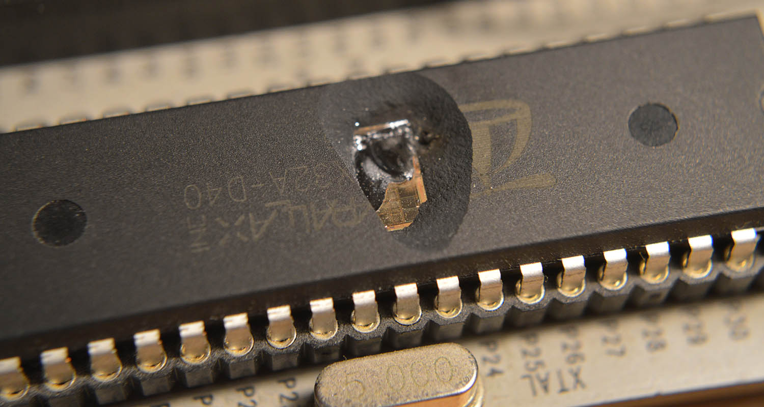
While working with high voltage there are new procedures to put in place. For those that say 120VAC isn’t high voltage, I’ve been used to working with 3.3-12VDC. The jump to 120VAC has had some very exciting times during prototyping and testing. First and foremost is when I crossed, and it was only a fraction of a second, a 120V live wire with an IO pin by accident. It was loud pop and I jumped back in my seat because it scared the bejesus out of me; it also blew apart my microcontroller. I had a good laugh afterwards and keep it attached to my shelf as a stark reminder to be careful.
All in all, my first project that I had everything from design to PCB manufacturing, I couldn’t be happier with the results. I can see why once someone learns the process of making a PCB, they stick to it going forward. I enjoy soldering as much as the next maker, and building a thing from scratch is great, but to have the board working like it’s supposed to with no extra wires anywhere, gives me great satisfaction. Creating PCB for projects feels like the the next evolutionary step in my maker skills.
If you are interested in building an A/C controller for simple on/off operation, it is very easy. 2 parts are needed, an Opto-isolator and TRAIC. If you want to add some intelligence to it, throw in a microcontroller and WAHLA!! you’re done. If you want to add dimming control, you will need a zero-cross detector, there just is no other way. There are plenty of forums out there with ½ bits of how to do this, and it took some reading to get all the actual details on the timing, at least the concepts of it. I highly suggest you have an oscilloscope that can read 400vpp handy as well; nothing replaces the ability to get a visual on what is happening. It really helped me understand how all the signals played with each other.
If you are interested in getting this board for yourself, I offer it in my shop. The board I made gives the option for someone to use whatever controller they want. I have the used a Propeller and an Arduino, but could be used a Raspberry Pi or countless other options.
.JPG)
Difficulty:
I give this project 4.5 stars because of the incredible learning curve of all the applications needed to complete it. There was everything from reading up on design concepts and previous application notes, understanding said application notes on which parts to swap out if needed because IC’s change over time, PCB design and layout, working with services overseas, and plenty of other aspects. This was a true start from nothing to finish product. It was my first custom PCB manufacturing run experience. Not ever project calls for this level of detail and development, but I will be looking for another one so I can go through these steps again. It has been a fantastic experience.